First look at HCX Network Extension HA feature

The High Availability feature for HCX Network Extension appliances was introduced in the version 4.3. This was a big deal, because if someone needed HA for their appliances that extend L2 networks (as this is a basic requirement for the resiliency) to the cloud and wanted to use VMware’s stack in particular, they had to deploy a pair of NSX-T standalone Edges on-prem leveraging NSX-T on the cloud side and setup a L2VPN.

VMware documentation mentions the following important prerequisites to consider before deploying HCX NE HA:

  • Network Extension HA requires the HCX Enterprise license.
  • Network Extension High Availability protects against one Network Extension appliance failure in a HA group.
  • Network Extension HA operates without preemption, with no automatic failback of an appliance pair to the Active role.
  • Network Extension HA Standby appliances are assigned IP addresses from the Network Profile IP pool.
  • The Network Extension appliances selected for HA activation must have no networks extended over them.

Also an interesting thing about NE in HA mode is the upgrade process:

In-Service upgrade is not available for Network Extension High Availability (HA) groups. HA groups use the failover process to complete the upgrade. In this case, the Standby pair is upgraded first. After the Standby upgrade finishes, a switchover occurs and the Standby pair takes on the Active role. At that point, the previously Active pair is upgraded and takes on the Standby role.

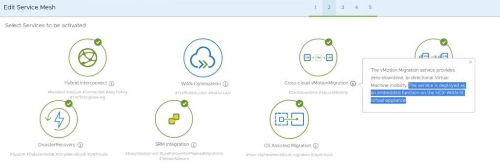
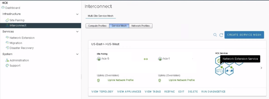
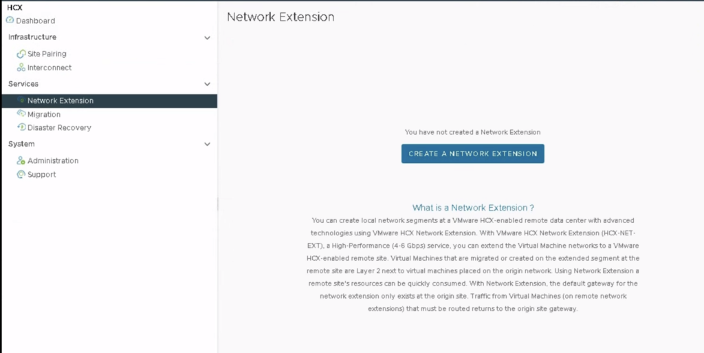
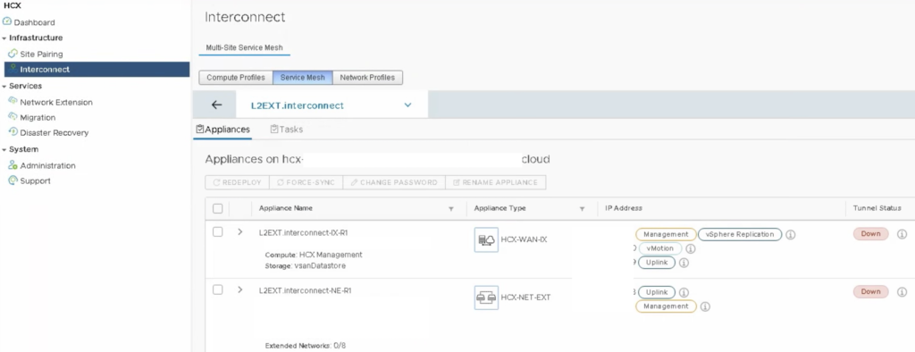
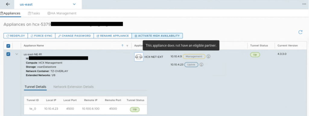
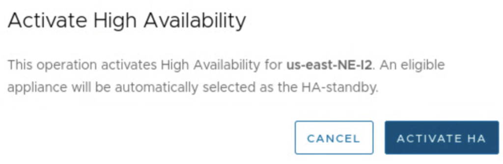
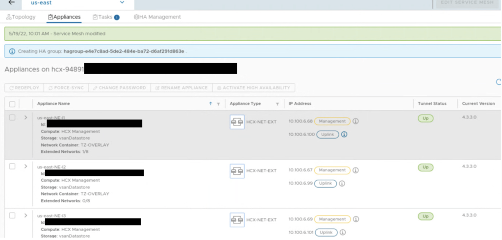
Let’s take a look at this new feature. In the HCX UI 4.3+, in the Interconnect -> Service Mesh -> View Appliances view, there is a new option called ACTIVATE HIGH AVAILABILITY.

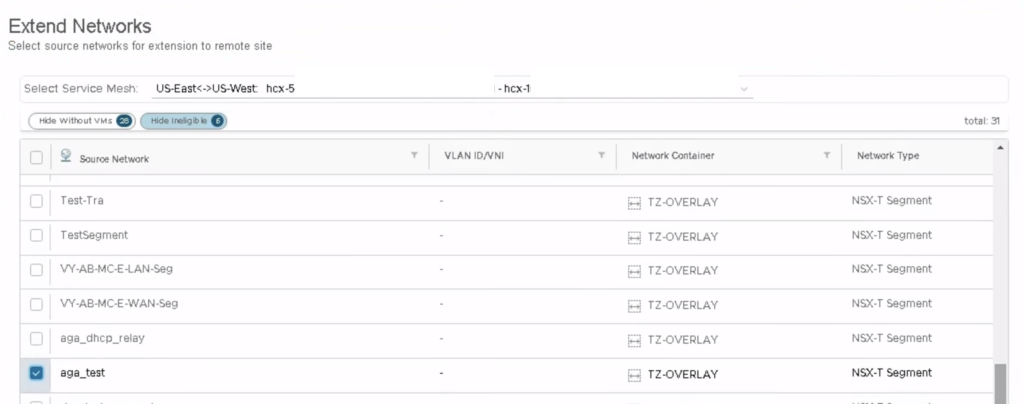
First, you need to have a pair of deployed NE appliances, the option won’t work when there is no eligible partner for HA.

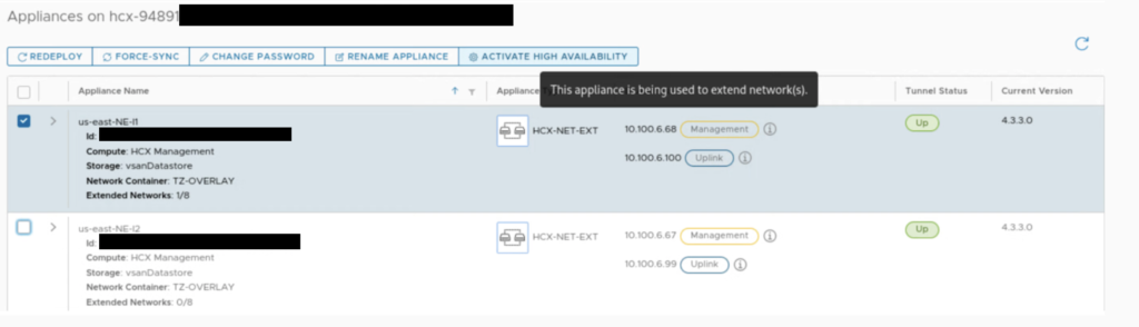
Also, system checks, if there are extended networks on an appliance that you select for HA.

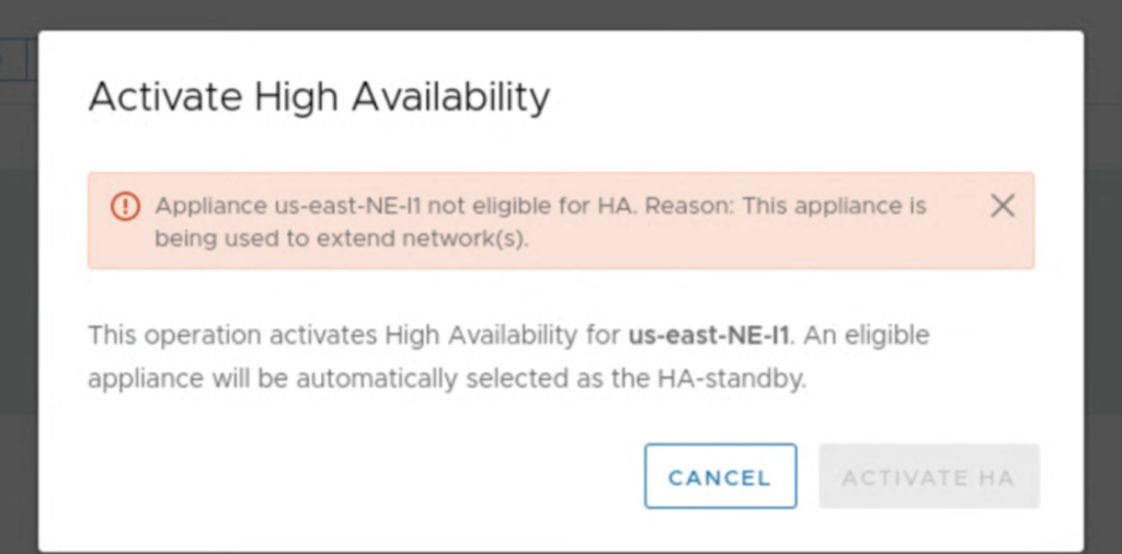
It can be a challenge to enable HA in an environment, where networks are already extended. In most cases this would require a downtime because we would have to unextend existing networks on NE appliances for the time of the HA configuration.

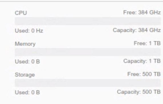
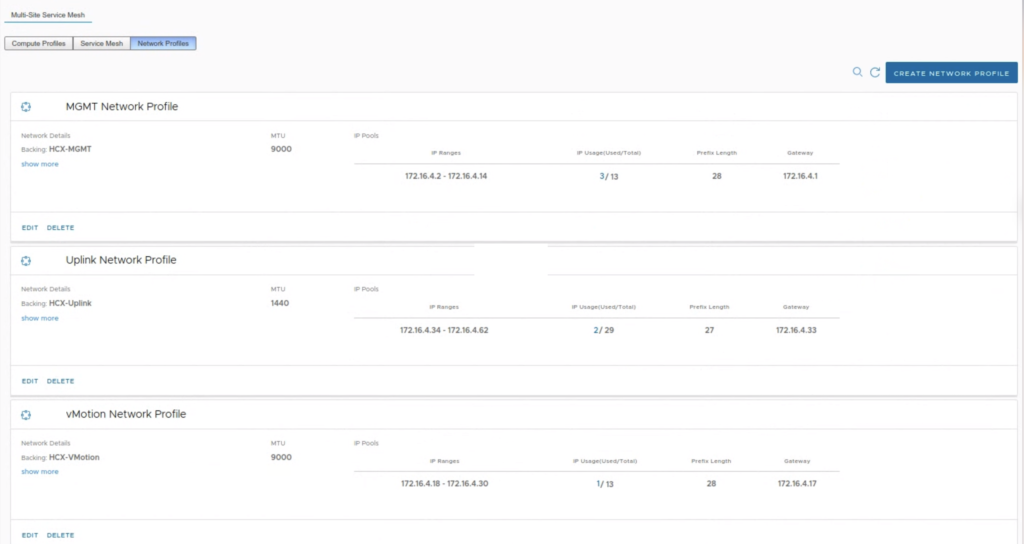
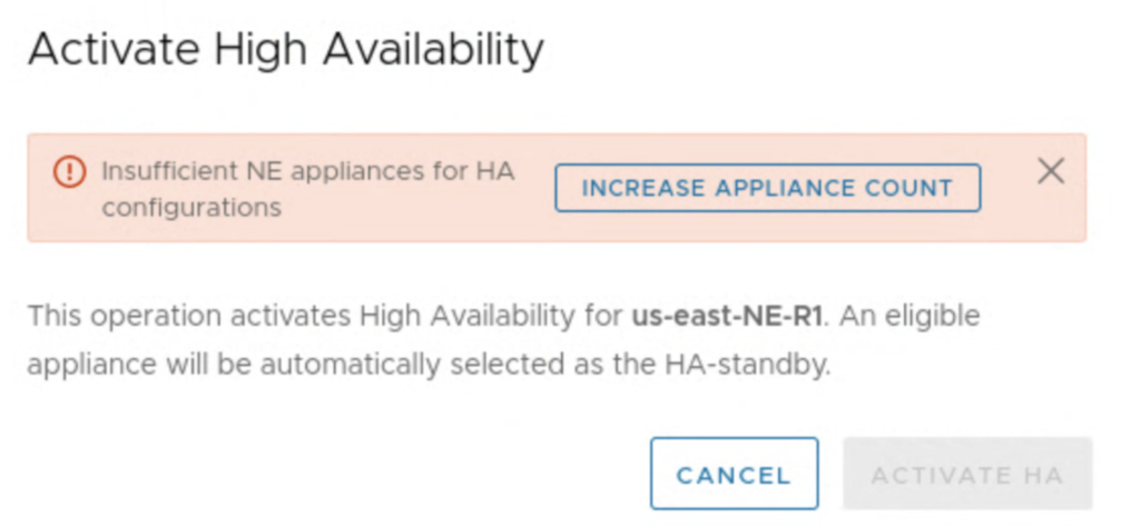
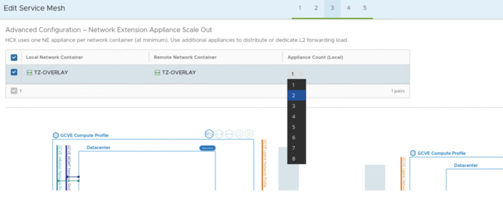
The system also checks if there are eligible NE appliances to activate HA feature and we get a button that is a shortcut to edit a Service Mesh and add more appliances. It can also be a challenge, if we don’t have a sufficient number of free IPs in our Network Profile’s IP pool. For 2 additional NE appliances on-prem and at the cloud side, we need one management IP and one uplink IP for each of them.

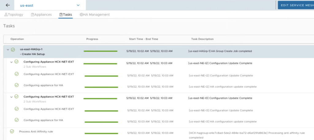
Once appliances are deployed, you only need to press a button Activate HA. Everything is configured for us, like in vSphere HA. New HA appliances create a HA group with a specific uuid.

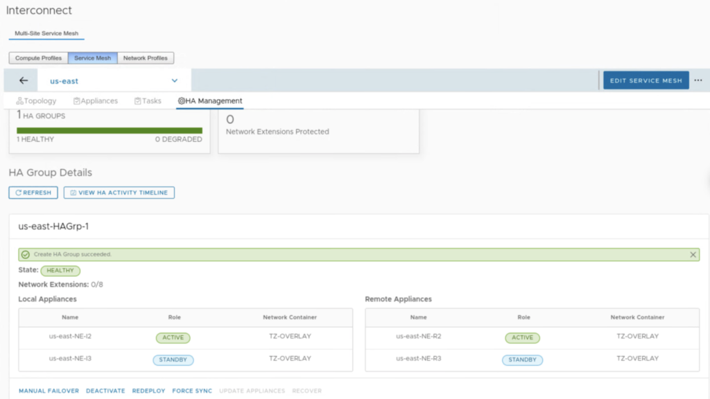
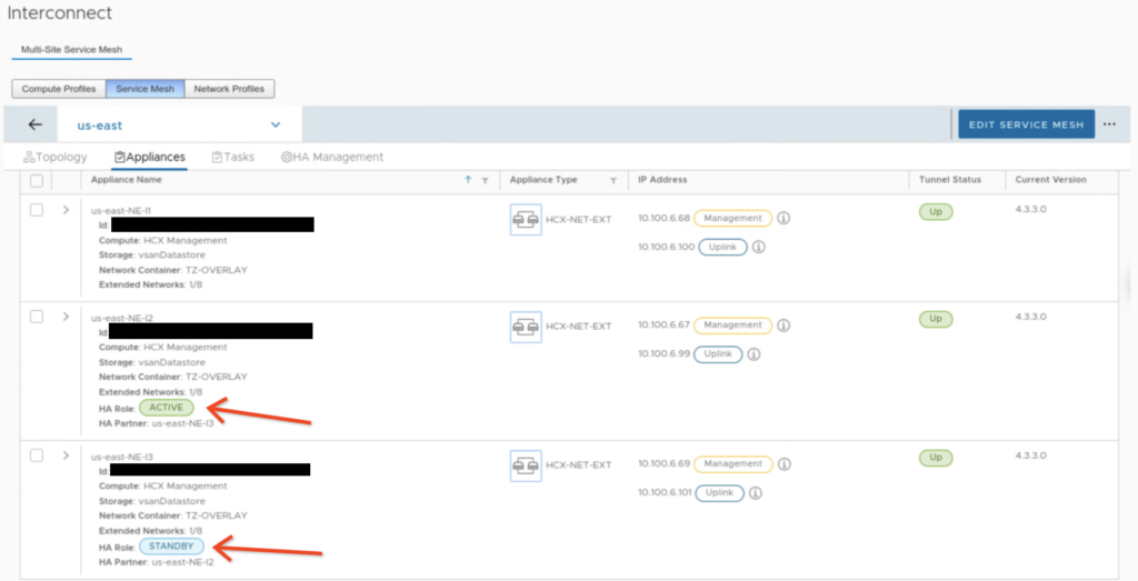
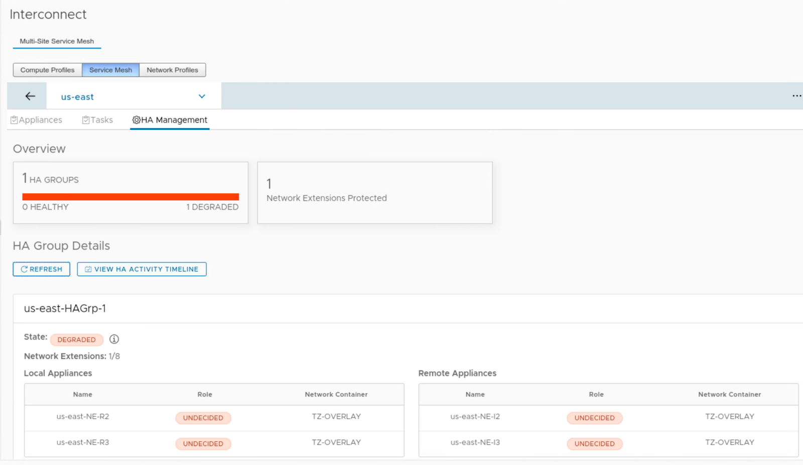
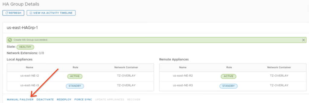
When HA is enabled, we can monitor its health in the HA Management tab. In the example below, we have 2 pairs: us-east-NE-I2 (on-prem) with us-east-NE-R2 (the cloud side) and us-east-NE-I3 (on-prem) with us-east-NE-R3 (the cloud side). Right after creation, the first pair is ACTIVE and the second is STANDBY.

Also in the Appliances view we can quickly check with NE appliance is ACTIVE and which one is STANDBY.

NE appliances with HA enabled can coexist with other NE appliances. This means we can still use single NE appliances for less critical workloads and HA groups only for selected networks.

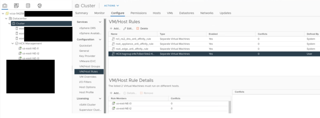
During a HA group creation, there is a VM/Host Rule created in a vCenter to make sure NE appliances in the same HA group won’t run on a same host.

After HA group is deployed, we can simulate a failure of one NE.

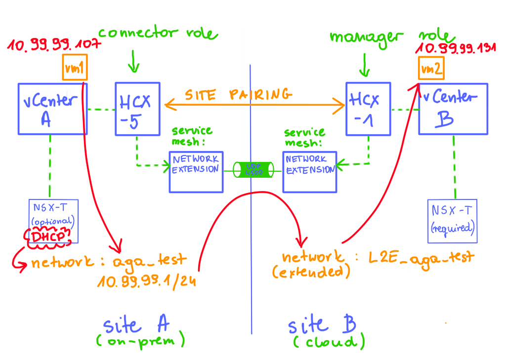
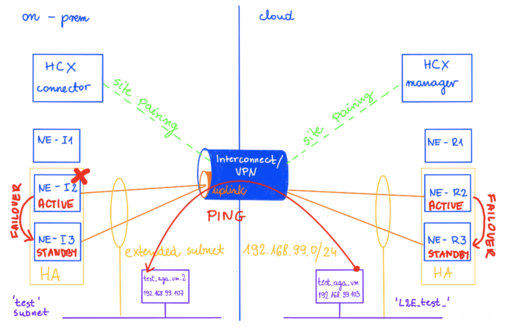
In this example I am using two sites, Sindey represents on-prem and Ashburn is my cloud side.

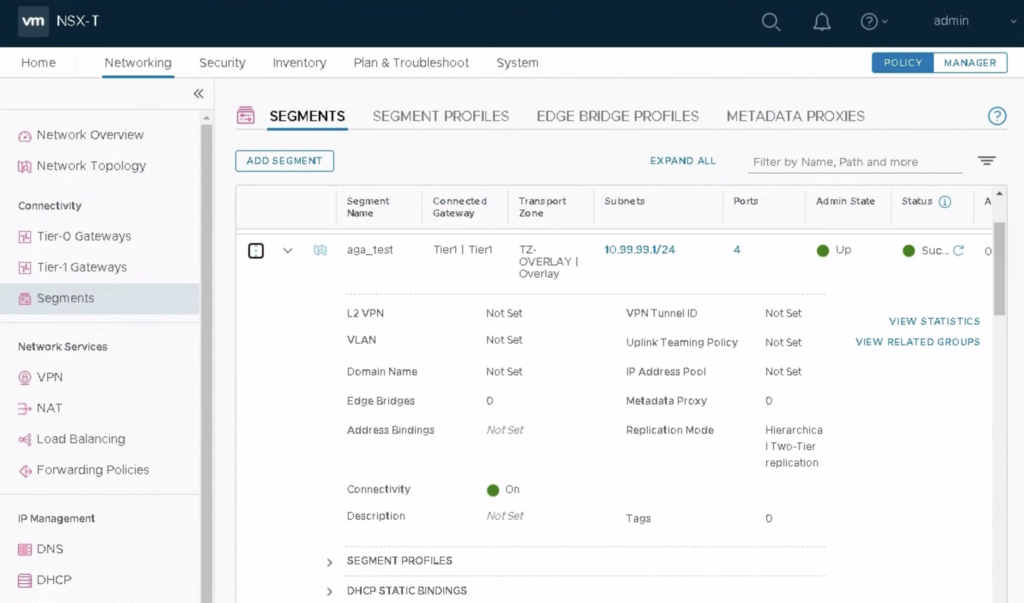
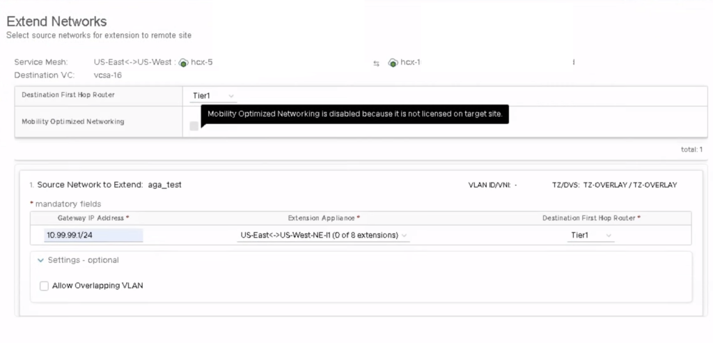
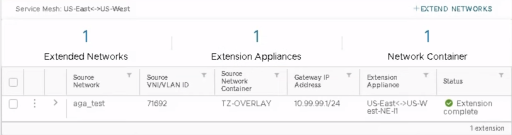
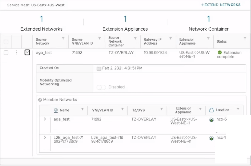
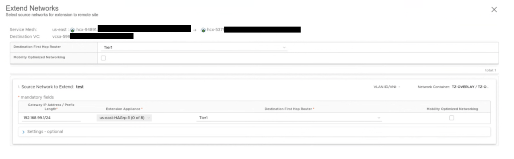
The network test 192.268.99.1/24 is extended on this new HA Group from on-prem (NE-I2 and NEI-3) to cloud (NE-R2 and NE-R3).

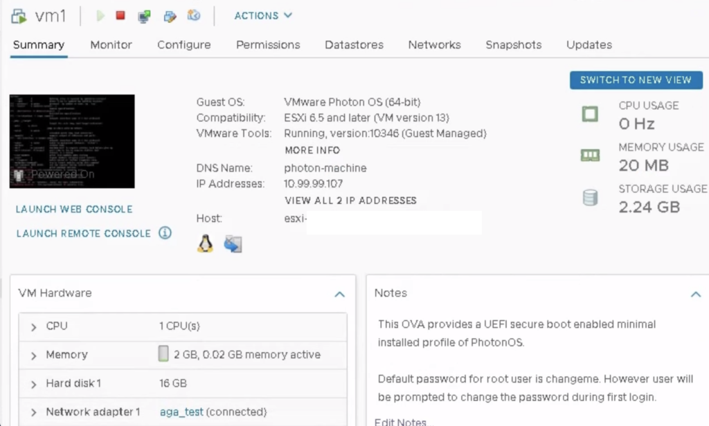
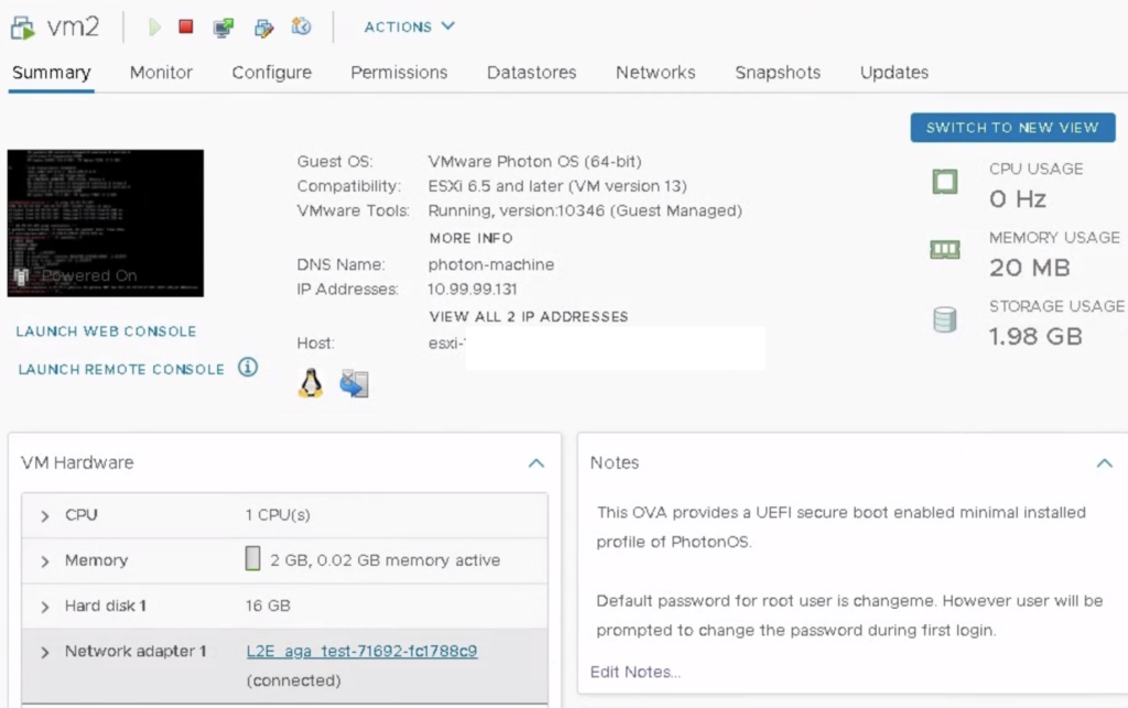
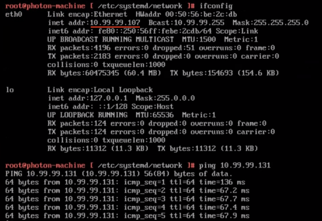
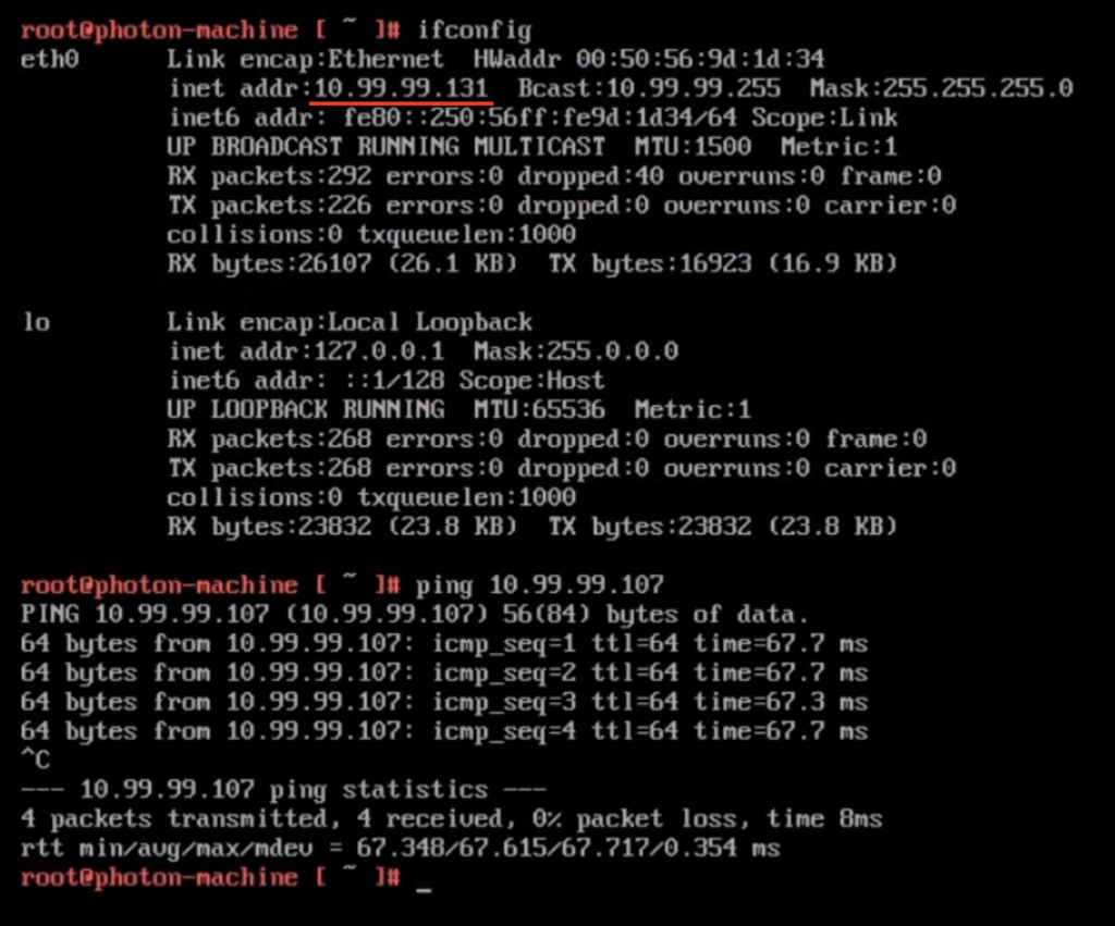
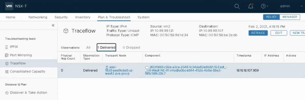
There is a vm test_aga_vm_2 (192.168.99.107) on-prem connected to the test subnet and on a cloud side, there is a vm test_aga_vm (192.168.99.103) on the extended network L2E_test. As VMs are at the opposite sides, we can have a ping running between them to test the connectivity during the NE failover.

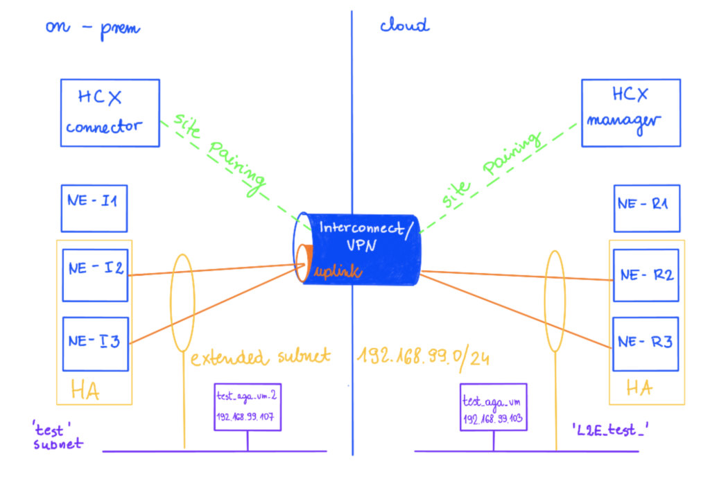
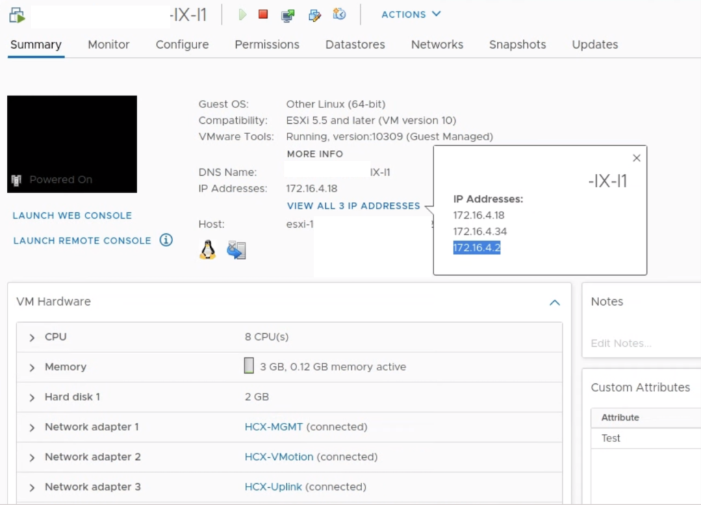
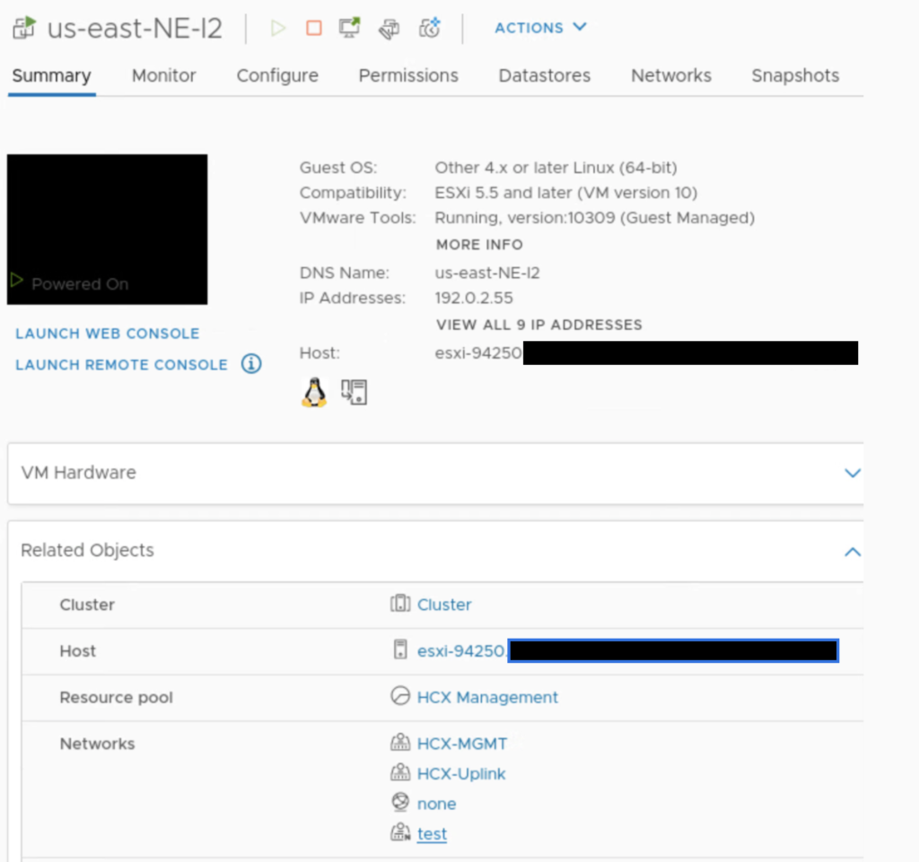
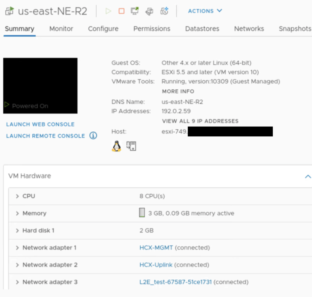
If you look closely at NE appliances, there is nothing specific to HA there, no specific HA subnet, only management, uplink and extended networks.

On the on-prem side, there is a test network attached to NE-I2, same for NE-I3.

On the cloud side, there is a L2_test network attached to NE-R2, same for NE-R3.

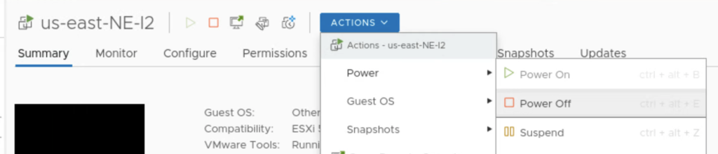
Now, to force a failover, I am shutting down an appliance on the on-prem: NE-I2.

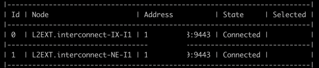
What happens next is there is a failover for the first pair of appliances: NE-I3 and NE-R3 become active. This is always a pair of appliances that changes the state, so in case NE-I2 is down, NE-R2 also fails over to NE-R3.

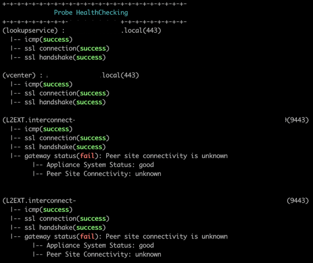
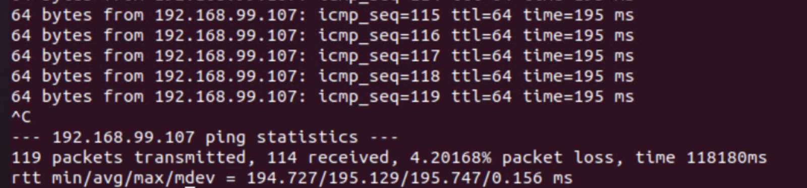
There is a small (as expected) packet loss observed and also it takes some time in the HA view in HCX UI to show the updated status of the appliances. The communication path between NE on-prem and NE on GCVE was restored and pings successful but the UI still showed a DEGREADED state for HA appliances for some time.

I lost 5 pings only during the failover, it was pretty quick.

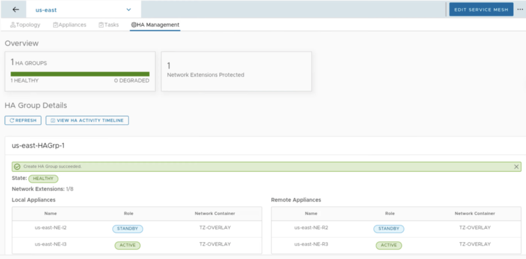
After few refreshes the UI shows a new state: HEALTHY with NE-I2 and NE-R2 being in the STANDBY and NE-I3 and NE-R3 in the ACTIVE state.

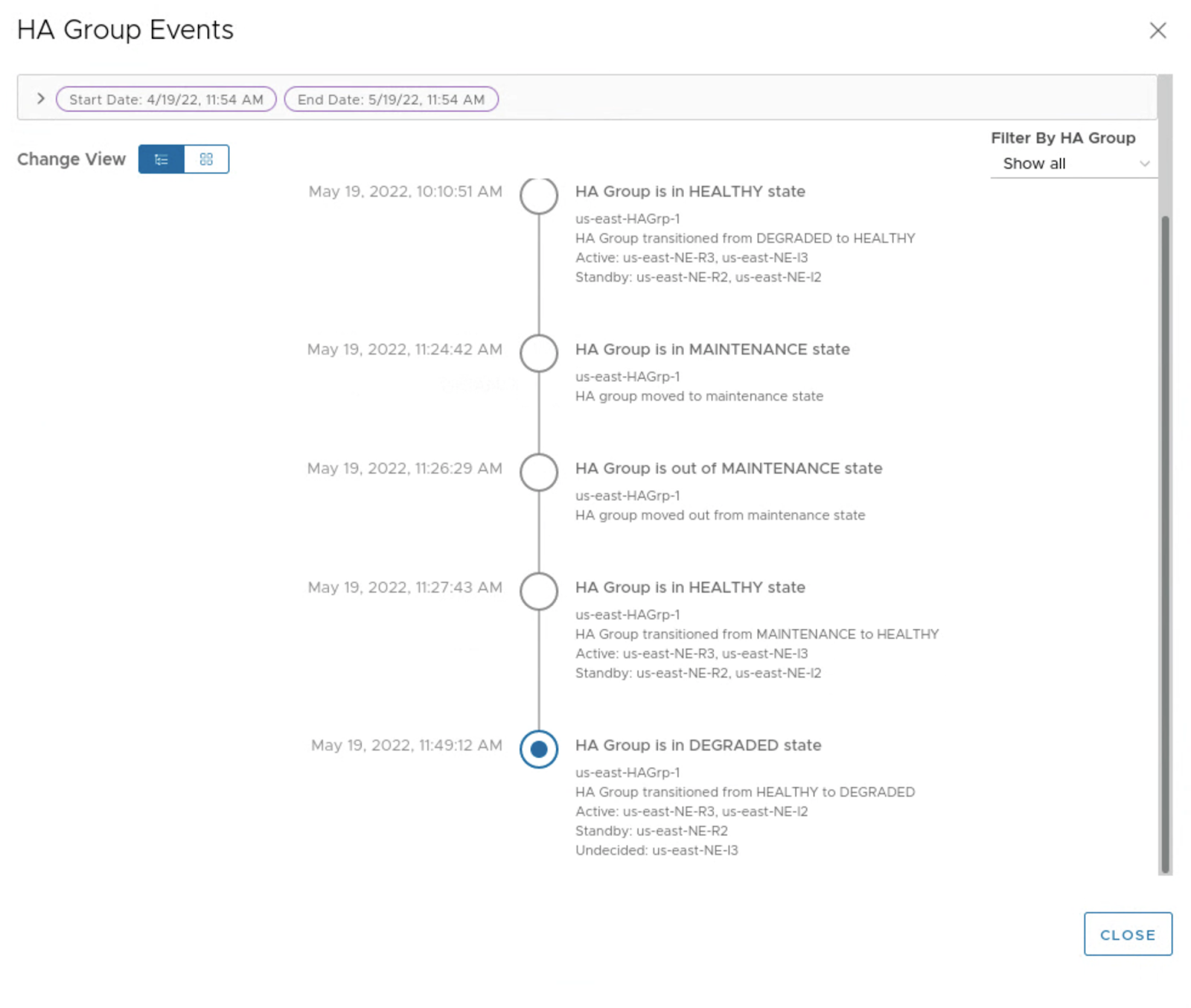
There is also an interesting option in the UI to view HA activity timeline. We can quickly check the HA history and states of the appliances.

If we don’t want to power off the appliances, we can use “manual failover” option to test HA.

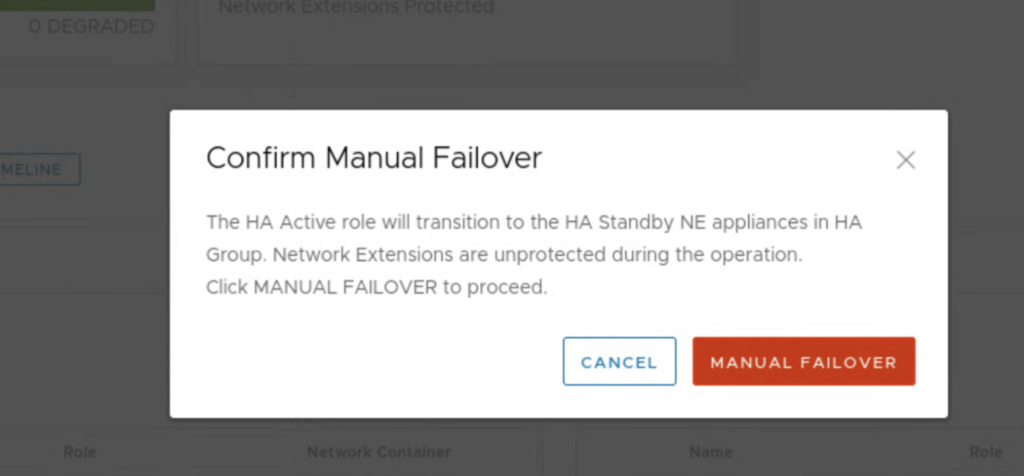
This one seems to be more graceful as I lost only 1 ping during this test.

HCX Mobility Agent aka “dummy host”

I bet many administrators have been surprised by this new ESXi appearing on a hosts list in vCenter UI after a HCX service mesh had been created for the first time. And for every HCX service mesh we create, there is one ESXi “host” being deployed.

Of course it is not a “real” host, it looks a little bit like its a nested one and its name seems to always be its HCX Interconnect (IX) appliance’s management IP. I think of it as a IX appliance’s alter ego 😉

New host on the Hosts list

It does have its own “VMware Mobility Agent Basic” license for 2 CPUs.

Mobility Agent License

But it not a typical nested ESXi, it’s a dedicated VMware Mobility Platform.

It has its own VMFS local datastore called ma-ds with a total “capacity” of 500 TB and 1 TB of RAM 😉 Fortunately, nothing is really taken from our physical resources.

In my case HCX service mesh Interconnect Appliance IX has 172.16.4.2 as management address, hence the host was named “172.16.4.2”.

IX appliance is a VM with many network interfaces, among the most important ones are HCX Management Interface, HCX vMotion Interface and HCX Uplink Interface. Uplink Interface is in fact the only one that is used to communicate with a target side, Management and vMotion Interfaces are used locally. The CIDR for those interfaces (and many other settings) are set during Network Profiles creation in HCX UI.

So what does this new dummy Host do?

Its job looks like a proxy for vMotion tasks between two paired HCX sides and allows for long distance cross vCenter vMotion. It is configured when the following service option is enabled: vMotion Migration service.

The vMotion Migration service provides zero-downtime, bi-directional Virtual Machine mobility. The service is deployed as an embedded function on the HCX-WAN-IX virtual appliance.

Configuring a service mesh with vMotion service

For HCX vMotion, we don’t need direct connectivity between source and target vCenters and their vMotion networks. A source IX appliance task is to trick a source ESXi to believe the destination ESXi for the vMotion task is local. Source ESXi “thinks” the target ESXi for the vMotion task is its local Mobility Agent host. A target IX appliance task is to trick a target ESXi to believe the vMotion task is local. Target ESXi “thinks” the source ESXi for the vMotion task is its local Mobility Agent host.

What source and target sides think is going on
vMotion from Source ESXi host to Source MA host
vMotion from Target MA Host to Target ESXi

What is really going on is transparent for the both source and target side. IX appliance on the source side acting as a receiving end for the vMotion task transfers the VM data via HCX Uplink Interface (IPsec tunnel) to the target IX that acts as the initiator of the vMotion task at the destination side.

What is really going on

This explains why there is a requirement for IX appliance to be able to communicate with ESXi over their vMotion networks.

https://ports.vmware.com/home/VMware-HCX

How to run basic performance tests for HCX uplink interface

I believe the build-in HCX perftest tool should be used for every freshly deployed HCX Service Mesh before we start migrating VMs between sites. Although the test is just a benchmark (it uses iperf3, it is single threaded), it will give us an idea how fast the VM migration will be and what can be expected in production. With HCX perftest tool testing is easier than with native iperf3 because we don’t have to provide/remember any IP addresses of appliances on-prem and in the cloud ;-).

To start the test we have to ssh to HCX manager as admin and select the IX appliance we want to test:

>ccli

>list

> go x -> select your service mesh appliance

> perftest -> to check available options:

Available Commands:
all perftest uplink, ipsec, wanopt and site in one command
ipsec iperf3 perf testing against ipsec tunnels
perf iperf3 perf testing
reachability Ping remote peers to test reachability.
site iperf3 perf testing between sites
status Query the test status.
uplink iperf3 perf testing against uplink
wanopt tcpperf testing against WANOPT tunnels

Available flags are:

Flags:
-h, --help help for uplink
-i, --interval uint32 Interval in second to report. Default is 1 second. (default 1)
-m, --msgsize uint32 TCP maximum segment size to send.
-P, --parallel uint32 Number of parallel streams. Default is 1. (default 1)
-p, --port uint32 Listen port on server side. Default is 4500. -p 22 also allowed. (default 4500)
-T, --runtimeout uint32 Individual test duration in second. Default is 1 minute. (default 60)
-t, --timeout uint32 Total timeout in seconds. Default 10 min. (default 600)
-v, --verbose Show details during testing if set
.

PERFTEST SITE: GENERAL TUNNEL CHECK

>perftest site
++++++++++ StartTest ++++++++++

---------- Site-0 [192.0.2.33 >>> 192.0.2.34] ----------
Duration Transfer Bandwidth Retransmit
server workload started
[ 4] 0.00-30.00 sec 13.8 GBytes 3.96 Gbits/sec 365 sender
[ 4] 0.00-30.00 sec 13.8 GBytes 3.95 Gbits/sec receiver
Done

---------- Site-0 [192.0.2.33 <<< 192.0.2.34] ----------
Duration Transfer Bandwidth Retransmit
[ 4] 0.00-30.00 sec 14.8 GBytes 4.24 Gbits/sec 167 sender
[ 4] 0.00-30.00 sec 14.8 GBytes 4.23 Gbits/sec receiver
Done

The iperf3 native commands that are used for this test with default values :

iperf3 -c 192.0.2.34 -i 1 -p 9000 -P 1 -t 30

iperf3 -s -p 9000 -B 192.0.2.33

PERFTEST IPSEC: TEST INSIDE IPSEC

> perftest ipsec
++++++++++ StartTest ++++++++++

---------- Ipsec-0 [t_0, 192.0.2.37 >>> 192.0.2.45] ----------
Duration Transfer Bandwidth Retransmit
server workload started
[ 4] 0.00-30.00 sec 3.40 GBytes 973 Mbits/sec 0 sender
[ 4] 0.00-30.00 sec 3.39 GBytes 972 Mbits/sec receiver
Done

---------- Ipsec-0 [t_0, 192.0.2.37 <<< 192.0.2.45] ----------
Duration Transfer Bandwidth Retransmit
[ 4] 0.00-30.00 sec 3.40 GBytes 974 Mbits/sec 0 sender
[ 4] 0.00-30.00 sec 3.40 GBytes 973 Mbits/sec receiver
Done

---------- Ipsec-1 [t_0, 192.0.2.38 >>> 192.0.2.46] ----------
Duration Transfer Bandwidth Retransmit
server workload started
[ 4] 0.00-30.00 sec 3.40 GBytes 973 Mbits/sec 0 sender
[ 4] 0.00-30.00 sec 3.40 GBytes 973 Mbits/sec receiver
Done

---------- Ipsec-1 [t_1, 192.0.2.38 <<< 192.0.2.46] ----------
Duration Transfer Bandwidth Retransmit
[ 4] 0.00-30.00 sec 3.40 GBytes 974 Mbits/sec 0 sender
[ 4] 0.00-30.00 sec 3.40 GBytes 973 Mbits/sec receiver
Done

---------- Ipsec-2 [t_2, 192.0.2.39 >>> 192.0.2.47] ----------
Duration Transfer Bandwidth Retransmit
server workload started
[ 4] 0.00-30.00 sec 3.39 GBytes 971 Mbits/sec 0 sender
[ 4] 0.00-30.00 sec 3.39 GBytes 970 Mbits/sec receiver
Done

---------- Ipsec-2 [t_2, 192.0.2.39 <<< 192.0.2.47] ----------
Duration Transfer Bandwidth Retransmit
[ 4] 0.00-30.00 sec 3.39 GBytes 971 Mbits/sec 1181 sender
[ 4] 0.00-30.00 sec 3.39 GBytes 970 Mbits/sec receiver
Done

The iperf3 native commands that are used for this test with default values :

iperf3 -c 192.0.2.45 -i 1 -p 9000 -P 1 -t 30

iperf3 -s -p 9000 -B 192.0.2.37

PERFTEST UPLINK: UPLINK INTERFACE CHECK

> perftest uplink

Testing uplink reachability…
Uplink-0 round trip time:
rtt min/avg/max/mdev = 66.734/67.081/68.135/0.578 ms

Uplink native throughput test is initiated from LOCAL site.
++++++++++ StartTest ++++++++++

---------- Uplink-0 [te_0, a.a.a.a >>> b.b.b.b] ----------
Duration Transfer Bandwidth Retransmit
server workload started
[ 4] 0.00-60.00 sec 5.20 GBytes 745 Mbits/sec 5116 sender
[ 4] 0.00-60.00 sec 5.20 GBytes 744 Mbits/sec receiver
Done
---------- Uplink-0 [te_0, a.a.a.a <<< b.b.b.b] ----------
Duration Transfer Bandwidth Retransmit
server workload started
[ 4] 0.00-60.00 sec 4.55 GBytes 652 Mbits/sec 6961 sender
[ 4] 0.00-60.00 sec 4.55 GBytes 651 Mbits/sec receiver
Done

The iperf3 native commands that are used for this test with default values :

iperf3 -c a.a.a.a -i 1 -p 4500 -P 1 -B b.b.b.b -t 60

iperf3 -c a.a.a.a -i 1 -p 4500 -P 1 -B b.b.b.b -t 60

Keep in mind that this is the only test that uses 4500 TCP port by default. If you have only 4500 UDP port open (this is the standard HCX Uplink requirement), your test will fail. You will see probably something like this:

"Command error occurs: Error calling peer [a.a.a.a.a:9445]: rpc error: code = Unavailable desc = all SubConns are in TransientFailure, latest connection error: connection error: desc = "transport: Error while dialing dial tcp b.b.b.b:9445: connect: connection refused"

PERFTEST ALL: ALL TESTS COMBINED

This test will run iperf for uplink, ipsec, wanopt and site.

>perftest all
========== PERFTEST ALL STARTING ==========
== WanOpt is Present ==
== TOTAL # of TESTs : 11 ==
== ESTIMATED TEST DURATION : 12 minutes ==
-T option to change individual test duration [default 60 sec]
-k option to skip 'perftest uplink' if tcp port 4500 or 22 not opened
== Are you ready to start ?? [y/n]:

USEFUL FLAGS

You can use more streams to saturate the pipe (-P), but keep in mind the test uses a single thread.

>perftest site -P 2
++++++++++ StartTest ++++++++++

---------- Site-0 [ 192.0.2.33 >>> 192.0.2.34] ----------
Duration Transfer Bandwidth Retransmit
server workload started
[ 4] 0.00-60.00 sec 16.8 GBytes 2.40 Gbits/sec 1498 sender
[ 4] 0.00-60.00 sec 16.8 GBytes 2.40 Gbits/sec receiver
[ 6] 0.00-60.00 sec 16.4 GBytes 2.35 Gbits/sec 1815 sender
[ 6] 0.00-60.00 sec 16.4 GBytes 2.35 Gbits/sec receiver
[SUM] 0.00-60.00 sec 33.2 GBytes 4.76 Gbits/sec 3313 sender
[SUM] 0.00-60.00 sec 33.2 GBytes 4.75 Gbits/sec receiver
Done
---------- Site-0 [ 192.0.2.33 <<< 192.0.2.34] ----------
Duration Transfer Bandwidth Retransmit
[ 4] 0.00-60.00 sec 19.0 GBytes 2.72 Gbits/sec 937 sender
[ 4] 0.00-60.00 sec 19.0 GBytes 2.72 Gbits/sec receiver
[ 6] 0.00-60.00 sec 19.5 GBytes 2.80 Gbits/sec 806 sender
[ 6] 0.00-60.00 sec 19.5 GBytes 2.79 Gbits/sec receiver
[SUM] 0.00-60.00 sec 38.5 GBytes 5.52 Gbits/sec 1743 sender
[SUM] 0.00-60.00 sec 38.5 GBytes 5.51 Gbits/sec receiver
Done

>perftest site -P 4
++++++++++ StartTest ++++++++++

---------- Site-0 [ 192.0.2.33 >>> 192.0.2.34] ----------
Duration Transfer Bandwidth Retransmit
server workload started
[ 4] 0.00-60.00 sec 9.22 GBytes 1.32 Gbits/sec 2108 sender
[ 4] 0.00-60.00 sec 9.21 GBytes 1.32 Gbits/sec receiver
[ 6] 0.00-60.00 sec 9.13 GBytes 1.31 Gbits/sec 2194 sender
[ 6] 0.00-60.00 sec 9.12 GBytes 1.31 Gbits/sec receiver
[ 8] 0.00-60.00 sec 9.20 GBytes 1.32 Gbits/sec 2288 sender
[ 8] 0.00-60.00 sec 9.19 GBytes 1.32 Gbits/sec receiver
[ 10] 0.00-60.00 sec 8.71 GBytes 1.25 Gbits/sec 2396 sender
[ 10] 0.00-60.00 sec 8.70 GBytes 1.25 Gbits/sec receiver
[SUM] 0.00-60.00 sec 36.3 GBytes 5.19 Gbits/sec 8986 sender
[SUM] 0.00-60.00 sec 36.2 GBytes 5.19 Gbits/sec receiver
Done
---------- Site-0 [ 192.0.2.33 <<< 192.0.2.34] ----------
Duration Transfer Bandwidth Retransmit
[ 4] 0.00-60.00 sec 10.2 GBytes 1.45 Gbits/sec 2071 sender
[ 4] 0.00-60.00 sec 10.1 GBytes 1.45 Gbits/sec receiver
[ 6] 0.00-60.00 sec 10.0 GBytes 1.43 Gbits/sec 1932 sender
[ 6] 0.00-60.00 sec 10.0 GBytes 1.43 Gbits/sec receiver
[ 8] 0.00-60.00 sec 10.2 GBytes 1.47 Gbits/sec 2149 sender
[ 8] 0.00-60.00 sec 10.2 GBytes 1.47 Gbits/sec receiver
[ 10] 0.00-60.00 sec 10.3 GBytes 1.47 Gbits/sec 2366 sender
[ 10] 0.00-60.00 sec 10.3 GBytes 1.47 Gbits/sec receiver
[SUM] 0.00-60.00 sec 40.7 GBytes 5.83 Gbits/sec 8518 sender
[SUM] 0.00-60.00 sec 40.7 GBytes 5.82 Gbits/sec receiver
Done

You can change MTU to test the best option (-m) and identify any MTU mismatch issues. You can also modify MTU settings in HCX Network Profile for Uplink profile.

> perftest site -m 1390
++++++++++ StartTest ++++++++++

---------- Site-0 [ 192.0.2.33 >>> 192.0.2.34] ----------
Duration Transfer Bandwidth Retransmit
server workload started
[ 4] 0.00-60.00 sec 30.6 GBytes 4.37 Gbits/sec 518 sender
[ 4] 0.00-60.00 sec 30.5 GBytes 4.37 Gbits/sec receiver
Done
---------- Site-0 [192.0.2.33 <<< 192.0.2.34] ----------
Duration Transfer Bandwidth Retransmit
[ 4] 0.00-60.00 sec 31.1 GBytes 4.46 Gbits/sec 270 sender
[ 4] 0.00-60.00 sec 31.1 GBytes 4.45 Gbits/sec receiver
Done

perftest site -m 9000
++++++++++ StartTest ++++++++++

---------- Site-0 [ 192.0.2.33 >>> 192.0.2.34] ----------
Duration Transfer Bandwidth Retransmit
server workload started
[ 4] 0.00-60.00 sec 29.4 GBytes 4.21 Gbits/sec 341 sender
[ 4] 0.00-60.00 sec 29.4 GBytes 4.20 Gbits/sec receiver
Done
---------- Site-0 [ 192.0.2.33 <<< 192.0.2.34] ----------
Duration Transfer Bandwidth Retransmit
[ 4] 0.00-60.00 sec 29.3 GBytes 4.19 Gbits/sec 307 sender
[ 4] 0.00-60.00 sec 29.2 GBytes 4.19 Gbits/sec receiver
Done

Extending a network with HCX Network Extension

Network Extension (NE) is a HCX service mesh appliance that helps to extend L2 network between two sites. It is used to provide network accessibility when migrating VMs between sites. Most popular use case is to use NE when migrating (via HCX or using other methods) VMs from on-prem site to cloud and back. It is also a little bit overused because the configuration is so easy and fast, we may want it stay there forever ;-). If this is the case, it is worth mentioning Mobility Optimised Networking (MON) NE feature would be needed for latency sensitive production workload. MON provides routing based on locality of source and destination VMs and prevents L2 Extension Tromboning. With MON VM in site B (remote) could communicate with other VMs in other segments without reaching site A where its gateway is located.

For my step by step demo I am using two locations: site A (on-prem) where network segment aga_test 10.99.99.1/24 is originally configured and site B (cloud) where the network aga_test will be extended. Site A uses NSX-T and DHCP is configured for my segment but NSX-T is not required, it can be any vSphere Distributed Switch VLAN/tagged network.

HCX-5 (site A, connector role) and HCX-1 (site B, manager role) are paired and NE service mesh appliances are deployed on both locations. NEs create unmanaged Encrypted Transport Tunnel between sites on the network link defined in Network Uplink Profile.

The goal is to enable L2 communication between vm1 in site A and vm2 in site B. Additional points are for making DHCP working on extended network.

aga_test is NSX-T 3.0 subnet: 10.99.99.1/24 with DHCP enabled
HCX service mesh with Network Extension appliance deployed between hcx-5 (site A) and hcx-1 (site B).
When NE appliance is deployed, we can create a Network Extension. Take a look at the description, “the default gateway for the network extension only exist at the origin site”, that is why MON may be useful.
We pick a network to extend from the list: aga_test.
This is the moment when we can enable MON. It is included in HCX Enterprise license. We provide gateway address and NE appliance that we want to use.
The network extension is ready in just a few minutes.
Service Mesh view provides more details on extended network: L2E_aga_test
vCenter on site B shows the extended network L2E_aga_test in the Network tab
Extended segment is visible in the Segments view in NSX-T on site B. Default Segment Security doesn’t allow DHCP so for the L2E_aga_test it has to be allowed.
Creating DHCP_Allow_Sec profile that allows to receive DHCP traffic for VMs on the extended network.
vm1 is deployed on Site A in aga_test network and has 10.99.99.107 address
vm2 is deployed on Site in L2E_aga_test extended network and got 10.99.99.131 address
vm1 pinging vm2
vm2 pinging vm1
The connectivity between vm1 and vm2 can be also verified using NSX-T Traceflow feature.

Basic HCX diagnostics

HCX is more just one component, but the main one is called HCX Manager. It is deployed as first and it is the one you can login to using https://FQDN_OR_IP:9443. Web UI is always a first step in troubleshooting because you can quickly check or restart services. And the most important, start SSH service to get to the console.

> ccli

Welcome to HCX Central CLI

Few simple commands that you can ran are:

> list

To list the connected service appliances:

> go 0

to select a specific appliance

> hc -d

to run a detailed healtcheck on the selected appliance, like this one…it is in a pretty bad shape:

> ssh

to connect to a selected appliance (no username and password required) to check networking, routing etc but also to view the logs. For Interconnect appliance (HCX-WAN-IX) /var/log/vmware/hbrsrv.log and /var/log/vmware/mobilityagent.log are the most valuable in troubleshooting.

To leave ccli just type > exit.

On HCX Manager the best destination for log analysis is: /common/logs/admin/app.log , /common/logs/admin/job.log and /common/logs/admin/web.log.

The most common issues that may occur during setup are mostly networking ones around interconnect between sites, Management Network, Uplink Network and vMotion Network.

And HCX Plugin in vCenter will show the following: tunnel status down

We can go through a very long list checking open ports running > ping, > netcat -vz : https://ports.vmware.com/home/VMware-HCX

We can take a shortcut as well (not sure if this is supported method but I believe we are good to go if we only want to edit something) and check HCX Mongo DB:

> mongo hybridity

> show collections

will list all the tables in the database. The table that is worth checking is the following (from what I checked it works on HCX Cloud connector/on-prem site where you can RUN DIAGNOSTICS on service mesh ):

> db.ServiceMeshDiags.find().pretty()

Look for entries:

"message" : "Diagnostics completed. There are 7 failed probes.",
"status" : "FAILED",

------------------------------

"status" : "FAILURE",
"error" : {
"output" : "",
"message" : "Failed to reach destination"
}
}
],
"status" : "ERROR",
"message" : "HCX-NET-EXT is unable to reach HCX-NET-EXT-PEER on the ports 4500. Please ensure firewall is not blocking the ports or routing is correctly configured."

------------------------------

{
"type" : "REACHABILITY_HTTPS_CONNECT",
"source" : "x.x.x.x",
"destination" : "x.x.x.x",
"sourcePort" : 0,
"destPort" : 443,
"destType" : "HCX-WAN-IX",
"protocol" : "TCP",
"status" : "FAILURE",
"error" : {
"output" : "",
"message" : "Failed to connect to target"
},

status" : "ERROR",
"message" : "HCX is unable to reach HCX-WAN-IX on the ports 443. Please ensure firewall is not blocking the ports or routing is correctly configured."

-----------------------------

"type" : "REACHABILITY_TCP_CONNECT",
"source" : "x.x.x.x",
"destination" : "x.x.x.x",
"sourcePort" : 0,
"destPort" : 8000,
"destType" : "Deployment_HostSystem",
"protocol" : "TCP",
"status" : "FAILURE",
"error" : {
"output" : "dial tcp x.x.x.x:8000: connect: no route to host",
"message" : ""
},

This table is a real time-saver!